

To create a simple LED circuit on a breadboard, you’ll need a few basic components: an LED, a resistor, a power source (like a battery or a bench power supply), and jumper wires. Let’s go through the process step by step, including the maths for selecting the correct resistor.
Components:
- LED (Light Emitting Diode)
- Resistor
- Power Source (e.g., a 9V battery or bench power supply)
- Breadboard
- Jumper Wires
Steps to Create the Circuit:
- Insert the LED into the Breadboard: LEDs have two legs, a longer one (anode) and a shorter one (cathode). Insert the LED into the breadboard, ensuring the legs are in different rows.
- Connect the Resistor: Attach one end of the resistor to the anode (longer leg) of the LED.
- Connect to Power Source: Use jumper wires to connect the free end of the resistor to the positive terminal of the battery and the cathode of the LED (shorter leg) to the negative terminal.
Maths for Selecting the Resistor:
The key formula here is Ohm’s Law:
V = IR where V is the Voltage, I is the current and R is the Resistance.
Steps:
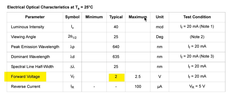
- Determine the Forward Voltage (Vf) of the LED: This is typically found in the LED’s datasheet. Let’s assume $$V_{f;}=2V$$
- Determine the Desired Current (I): LEDs typically operate around 10-20mA. Assuming 20mA, which is 0.02A.
- Calculate the Supply Voltage $$V_s$$: This is the voltage of your power source, say a 9V battery.
- Calculate the Required Resistance (R) using the formula: $$R=\frac{V_s-V_f}I$$
Example Calculation:
Given: $$V_s=9V,\;Vf=2V,\;and\;I=0.02A$$
$$R=\frac{V_s-V_f}I=\frac{9V-2V}{0.02A}=\frac{7V}{0.02A}=350\Omega$$
So, you’d need a resistor of approximately 350 ohms. It’s common to use the nearest standard resistor value, which in this case might be 330 ohms. This will allow a little more current than our calculation which will mean it is slightly brighter and will reduce it’s life slightly. Best practise would be to use one slightly higher.
Additional Tips:
- Always check the datasheet of your LED for the exact forward voltage and current ratings. I have included a typical datasheet but they will vary depending on the manufacturer and model of the LED.
- It’s better to err on the side of a slightly higher resistance which I explained a moment ago.
With these steps and calculations, you can confidently set up a simple LED circuit on a breadboard. Remember, experimenting is key in electronics, so don’t hesitate to try different configurations and see what works best for your needs.
The next lesson will be to flash the LED using transistors. After that we will attempt the same using a 555 timer.


Leave a Reply